In a continuous sand filter the water passes the filter bed in upward direction. The flow of water through a porous medium results in a hydraulic pressure drop. We call this pressure drop the filter bed resistance. The actual value of this filter bed resistance is measured by reading the difference in head in the feed pipeline to the filter and the filtrate level in the filter, as per the figure.  

Clean filter bed resistance

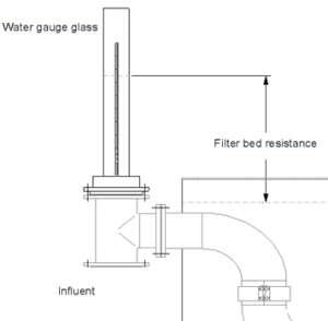
Either by using apressure indicator or by simply measuring the water level in the de-aeration pipe at the top of the filter.


Filter bed resistance

The filter bed resistance,  Hfilter bed, can be divided into two components:

                                                Hfilter bed = H0 + Hdeposition                                                                                                 (1)

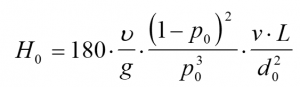
H0 is referred to as the clean bed resistance; this is the hydraulic resistance due to the water flow of a clean filter bed, without any deposits in the pore space.

The second component, Hdeposition, represents the additional filter bed resistance due to deposits in the pore space of the filter medium.

In this blog we will show how the clean bed resistance is calculated. If you know what the clean bed resistance should be, you are able to interpret the actually measured filter bed resistance. If you measure a value close to the clean bed resistance, your filter bed is more or less clean. The other way around: if you measure a value higher than the calculated clean bed resistance, the additional head loss is due to the presence of deposits in the pores of the filter bed.


Calculating clean bed resistance H0

The clean bed resistance Ho (m) is a function of several parameters and can be described by the Carman-Kozeny equation:

With:

v             =             kinematic viscosity (m2/s)

g             =             gravitational acceleration (m/s2)

p0           =             porosity (-)

v             =             filtration rate (m/s)

L             =             filter bed height (m)

d0           =             specific diameter of the filter medium (m)

The specific diameter is a characteristic diameter which is influenced by grain size as well as uniformity and form of grains. This subject will be discussed in another blog.

(2)

The kinematic viscosity depends only on water temperature via:

With:


T             =             water temperature (ºC)

(3)

With:

Q            =             feed flow (m3/s)

n             =             number of filters in operation (-)

Af           =             filtration area per filter (m2)

(4)

Let’s show an example to quantify the clean bed hydraulic resistance, assuming a plant which is characterized in table 1:

Parameter

Symbol

Value

Value used in

equations

Feed flow

Q

120 m3/h

0.033 m3/s

Number of filters in operation

n

2

2

Filtration area per filter

Af

5.0 m2

5.0 m2

Temperature

T

8 oC

8 oC

porosity

po

40%

0.40

Filtration rate

v

12.0 m/h

0.0033 m/s

Filter bed height

L

1.5 m

1.5 m

specific diameter of the filter medium

do

1.4 mm

0.0014 m

Gravitation acceleration

g

9,81 m/s2

9,81 m/s2

The output is indicated in the table below:

Parameter

Equation

Value

Kinematic viscosity

(3)

1.38*10-6 m2/s

Clean bed resistance Ho

(2)

0,36 m

Summary

The calculations allow you to determine the clean bed resistance in function of the operating parameters. It also allows you to compare the clean bed resistance with the actual filter bed resistance, which you can measure in practice. If you find out that the actual filter bed resistance is much higher than the clean bed resistance, your system might be overloaded or offset. A further analysis might be appropriate.