In a continuous filter, the filtration process takes place simultaneously with the washing of the filter media. The washing process consists of two principles: the highly turbulent airlift transport of dirty sand from the bottom of the filter to the top of the filter and the final separation of sand grains and solids. In this blog we will highlight the washing process and characteristics.
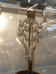
The air lift transports a mixture of sand and impurities of the bottom of the filter to the washer, which is located in the center of a filter, in the filtrate area. See figure 1. The main function of the washer is to separate clean sand grains from impurities.
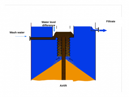
Figure 1. The main function of the washer is to separate clean sand grains from impurities
Airlift
transport
Sand and solids are sucked into the airlift at the bottom part of the filter due to the feed of compressed air into the airlift. This principle is well known in dredging and very effective for vertical transport of sand. During the vertical transport of the mixture of sand, solids, air and water the sand grains are effectively washed by the air and water scour, prior to discharge into the washer assembly at the top of the filter.
The typical amount of air required for the airlift transport and scouring is 1.0 – 1.5 Nm3 of air per ton of filter sand lifted. The typical amount of water lifted together with the sand/solids mixture is 0.3 – 0.5 m3 per ton of sand lifted.
Washer
assembly
The cross section of the washer assembly
is indicated in figure 2. The core part of the washer is the labyrinth, which separates the clean sand grains from the solids. The separation mechanism is based upon the density difference between the (heavy) sand grains and the light solids. Filtrate water flows upward through the washer labyrinth, forced hydraulically by a pre-set water level difference between wash water and filtrate. This level difference can be manually set between 5-10 cm. The main function of the washer is to separate sand grains from solids.
How to arrange this? Simply by creating an upward high enough flow velocity of water through the washer labyrinth to wash out solids without losing sand grains. The design water velocity through the washer is the key to this all. Let’s illustrate this with some calculations. Assume the smallest sized sand grain is 0.5 mm. Such a grain has a settling velocity of about 500 m/h. Solids retained in the filter normally settle at a rate less than 5 m/h. Hence the washer is designed to create up flow velocities of 50 – 100 m/h. High enough to wash out solids, without washing out sand grains.
Total wash
water flows
As explained the total wash water flow in a continuous filter is the sum of:
– The water which is lifted with the grains/solids in the airlift (also indicated as the “pump water”).
– The filtrate water used to wash out the solids in the washer labyrinth.
As a rule of thumb you should have a total wash water flow which is in the range of 0.8 – 1.0 m3/h per m2 of filter area in a standard continuous sand filter plant. Hence a 5 m2 continuous filter is generating a continuous wash water flow which is in the range of 4.0 – 5.0 m3/h. Be aware this total wash water flow is not related to the feed flow, as it is fully governed by the airlift characteristics and the washer assembly configuration.
Trouble shooting
What if you checked your wash water flow and discovered your data are either too high or too low? We’ll explain what might happen and what you could do.
If the wash water flow is too low you do not have enough cleaning capacity and this might cause the filter performance to decrease. You might check the water level difference over the washer assembly and if there is room to increase this level difference by adjusting the wash water weir this might solve things.
If the wash water flow is too high, this might lead to sand blockages in the washer, wash out of sand and loss of filter media. It is obvious that you would like to avoid this from happening. You might check the water level difference over the washer assembly and if possible reduce the level difference by adjusting the wash water discharge weir. Always secure to maintain the level difference at a minimum level of 50 mm.
If you cannot manage to get your wash water flows within the acceptable range and would like to use some assistance, please contact us.